Search 4,717 docs, articles & videos from the world’s leading Automotive part manufacturers

Mechanic or computer engineer?
Wednesday 3rd June 2015

Since the introduction of Controller Area Networks (CAN) in cars in the 1983, Bosch has continued to improve this method of communication between control modules. Modern vehicles have up to 70 modules communicating on various bus networks. This added complexity has many garages running for cover. But with training, the mysteries of CAN can be unfolded, most after a short delve into CAN diagnostics. Understanding it can be very interesting, and not such a dark and mysterious subject.
CAN is simply a group of modules sharing information over a two wire twisted pair. Admittedly they look complicated in the beginning, but let's break it in to manageable chunks.
Powertrain or high speed CAN
Probably the most notable, as we get calls continually on this network. This network is normally running at a speed of 500kbits, exchanging data between Engine, ABS, Transmission, SRS Instruments and Power Steering, just to name a few. This reduces the need for duplication of sensors, reducing vehicle weight.
The diagnosis of CAN
On CAN enabled vehicles, pin 6 and 14 of the diagnostic plug are the high and low CAN connectors of the power train Bus. The first test is to check the resistance across these two terminals. A good CAN circuit will register 60 ohms. If you get 120 ohms, one circuit has an open circuit or break in the network. If you get a short circuit here, the network will not work.
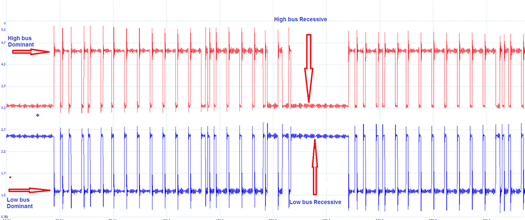
The CAN network runs on a 2.5 volt Recessive signal. This means the CAN high bus (red trace in figure above) has 2.5 volts present until a message is sent, changing to 3.5 volts for each data bit. On the low bus (blue trace in figure above) 2.5 volts is present until a message is sent and then it changes to 1.5 volts for each data bit.
If you look at these two signals, the message bits are a mirror image of each other. This is done to check for errors, both buses change by one volt in opposite directions. As the wires are twisted together, they are resistant to electromagnetic interference.
The 3 main CAN networks, as they communicate at different speeds, pass through a central gate way. The job of the Gateway module is to manage the message traffic on the different buses. Each Module on the network is normally a master, this type of system now common is known as a multi master system. Making it the responsibility of each module to control the transmission rate and message timing individually.
One common problem is bus loading. This where the bus has too much traffic, normally a bus can run up to 50% loading. Any more leaves no space for messages to get on the bus. A faulty module can be occupying too much time on the bus, removing this suspect module from the network can see the bus traffic significantly reduced, allowing normal traffic to resume.But with the obvious fault codes from other modules reporting this missing module.
I hope this informs some technicians not to be afraid of CAN.
For your risk-free trial on the eXponentia Technical Helpline, ring us on +353-(0)1-905-9500.
